
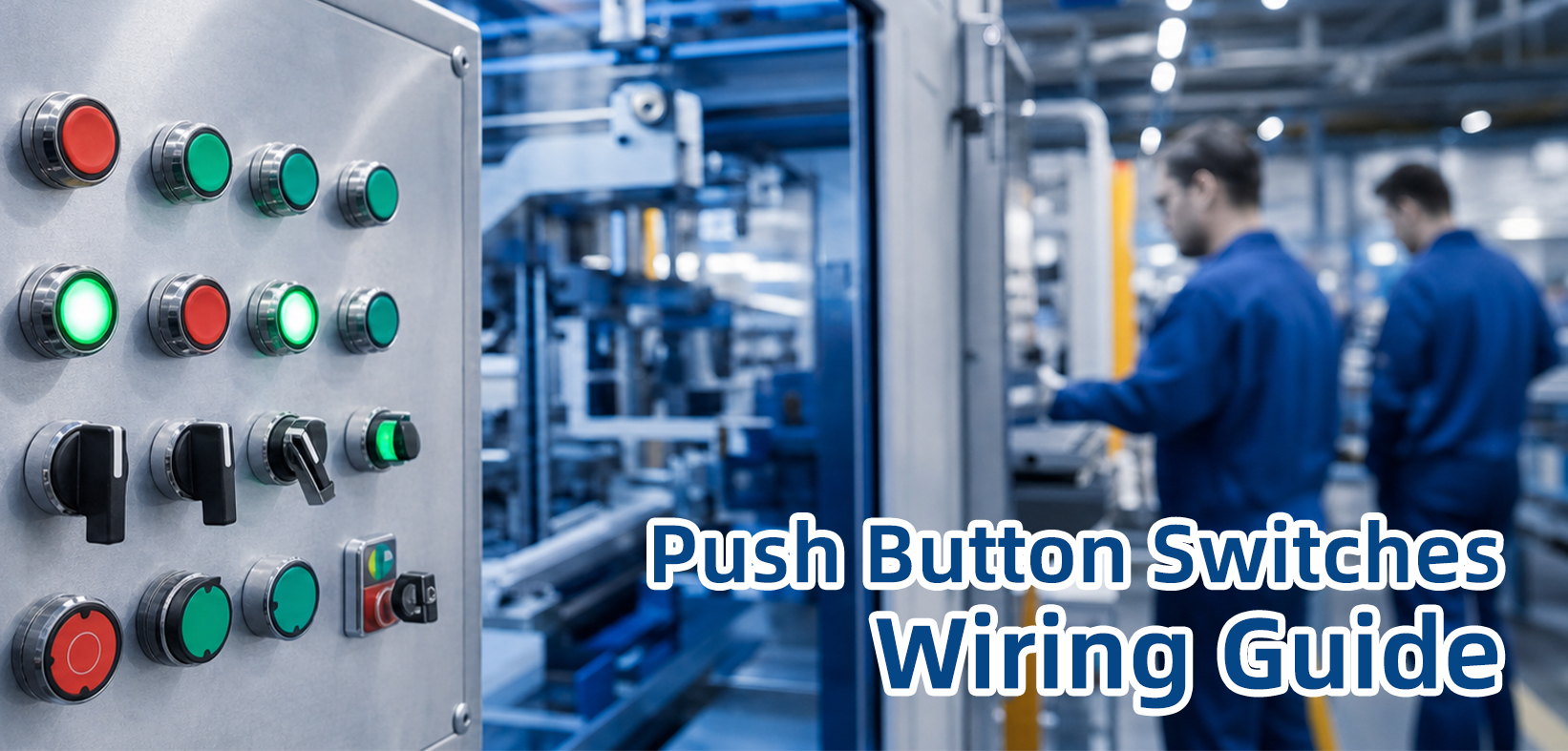
Industrial push button switches are one of the most commonly used control components in automation equipment, electrical control panels, machinery, and industrial systems.
Understanding how to correctly wire a push button switch is essential for engineers, electricians, machine builders, and maintenance technicians.
This complete industrial push button wiring guide explains how to connect normally open (NO), normally closed (NC), LED illuminated push buttons, PLC control buttons, and emergency stop switches.
It also covers terminal identification, wiring methods, application examples, troubleshooting tips, and selection considerations for industrial environments.
Whether you are installing a 22mm panel mount push button, replacing a machine control switch, or designing an automation control cabinet, this guide provides practical wiring knowledge to help you select and connect the correct push button configuration.
Table of Contents
- 1.Push Button Switch Basics
- 2.Understanding NO and NC Contacts
- 3.How to Wire a Normally Open 22mm Push Button
- 4.How to Wire a Normally Closed Metal Push Button
- 5.How to Wire an LED Illuminated Push Button
- 6.How Does a Push Button Connect to PLC?
- 7.How to Connect Emergency Stop Button Wiring?
- 8.Common Push Button Wiring Mistakes
- 9.Push Button Wiring Selection Guide
- 10.Frequently Asked Questions
Push Button Switch Basics
What Is a Push Button Switch?
A push button switch is a manually operated electrical switching device that controls the flow of electrical signals by pressing or releasing an actuator.
When the button is pressed, the internal contacts change their electrical state, allowing or stopping current flow in a control circuit.
Industrial push button switches are widely used in:
Industrial automation machines,Motor control panels,Production line equipment,CNC machines,Packaging machinery,Robotics and PLC control systems,Safety control systems
A complete understanding of push button structure, working principle, and applications helps engineers choose the correct contact type, voltage rating, mounting size, and indicator function.For detailed information about push button structure and applications, you can also refer to our article: What Is a Push Button Switch
Common Push Button Terminals Explanation
Before wiring an industrial push button, it is important to identify the terminal markings.Different manufacturers may use different symbols, but most industrial push buttons follow similar terminal definitions.
| Terminal | Meaning | Function |
|---|---|---|
| COM | Common Terminal | Shared connection point for NO and NC contacts |
| NO | Normally Open | Circuit closes when the button is pressed |
| NC | Normally Closed | Circuit opens when the button is pressed |
| LED + / LED - | LED Indicator Power | Provides power for illuminated indication |
Understanding NO and NC Contacts
The most important factor when wiring an industrial push button is understanding the difference between normally open (NO) and normally closed (NC) contacts.The contact configuration determines how the control signal behaves before and after pressing the button.
What Does Normally Open (NO) Mean?
A normally open push button contact means the electrical circuit remains open under the normal resting condition.
There is no current flow because the contact points are separated.
- Normal State: Open circuit
- Button Pressed: Contact closes and allows current flow
NO push buttons are mainly used when a temporary control signal is required.
Typical applications include:
Machine start buttons,Motor start commands,Trigger switches,PLC digital input signals,Operator control panels
For example, when an operator presses a machine start button, the NO contact closes and sends a signal to the PLC input module.The PLC then executes the programmed logic and activates the motor or actuator.
What Does Normally Closed (NC) Mean?
A normally closed push button contact maintains a closed circuit during the normal resting condition.
Electrical current can continuously pass through the contact until the button is pressed.
- Normal State: Closed circuit
- Button Pressed: Contact opens and interrupts the circuit
NC contacts are commonly used for stop functions and safety-related applications because they provide fail-safe protection.If a wire breaks or the circuit loses connection, the control system can detect the abnormal condition.
Typical NC applications include:
Machine stop buttons,Emergency stop circuits,Safety relay systems,Protection circuits,Industrial equipment interlock systems
NO vs NC Push Button Comparison
| Feature | NO Contact | NC Contact |
|---|---|---|
| Normal State | Open Circuit | Closed Circuit |
| Pressed State | Closed Circuit | Open Circuit |
| Typical Application | Start / Trigger / PLC Input | Stop / Safety / Emergency Stop |
Choosing between NO and NC depends on the required control logic and safety requirements.For simple command signals, NO contacts are usually preferred, while safety-related circuits generally require NC contacts to achieve fail-safe operation.
How to Wire a Normally Open 22mm Push Button?
How Does a Normally Open Push Button Work?
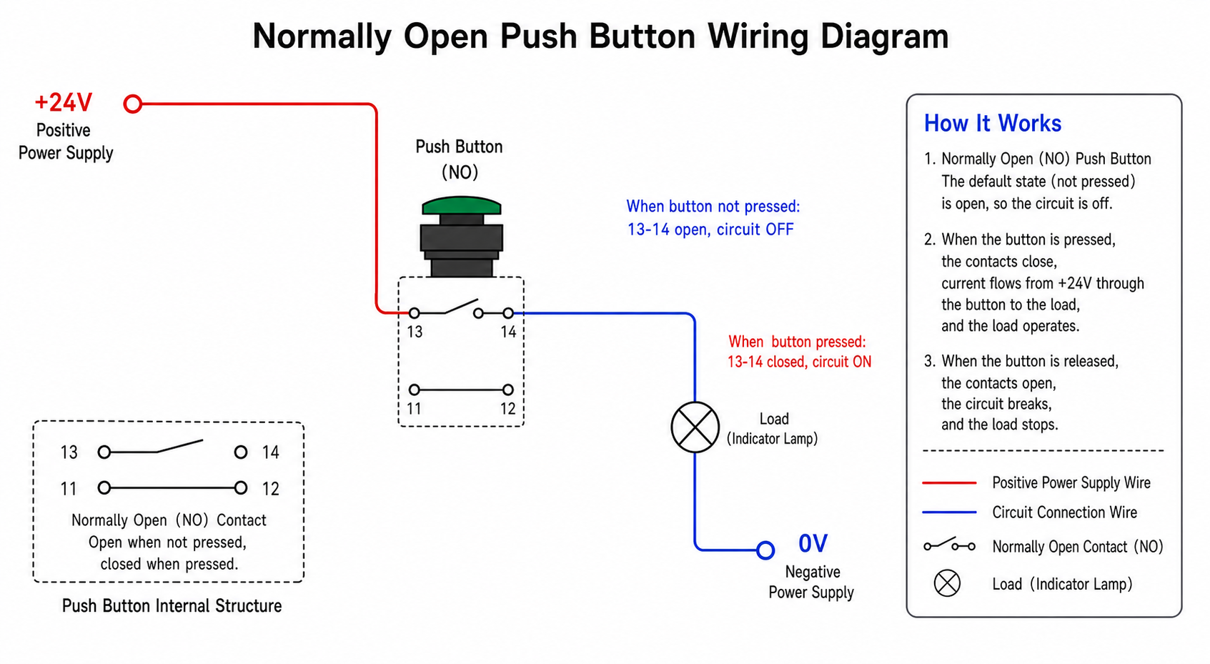
A normally open (NO) 22mm push button switch is one of the most commonly used industrial control switches.The term "normally open" means that the internal contact remains disconnected when the button is not pressed.
When the operator presses the push button actuator, the internal contact mechanism moves and closes the electrical path between the COM terminal and NO terminal(The normally open button switches produced by some suppliers will have 2 terminal feet without any identification, and do not distinguish between COM terminal and NO terminal feet).This allows current or a control signal to pass through the circuit.
In industrial automation systems, a NO push button is normally used as a command input device.The button itself does not directly control the motor or machine load in most cases.Instead, it sends a signal to a relay, contactor, or PLC input module, which then controls the final output device.
- Released Button: COM and NO terminals are disconnected
- Pressed Button: COM and NO terminals become connected
- Main Function: Generate a temporary control signal
Simple NO Push Button Wiring Diagram
A basic industrial NO push button wiring example is shown below.This example uses a 24V DC control circuit, which is widely used in industrial automation control panels.
24V DC +
|
|
Push Button COM
|
Push Button NO
|
PLC Input / Relay Coil
|
0V DC -
In this wiring method, pressing the button completes the circuit and sends a 24V control signal to the PLC input or relay.After receiving the signal, the control system executes the programmed operation, such as starting a motor, opening a valve, or activating a machine sequence.
Step-by-Step Connection of a 22mm NO Push Button
Before wiring a 22mm industrial push button, make sure the voltage rating, contact type, and terminal markings match your application requirements.
- Prepare the required components:
Typical components include: 22mm panel mount NO push button switch、24V DC power supply or control voltage source、PLC input module or relay、Control wires、Terminal blocks - Identify the terminals: Locate the COM and NO terminals on the push button contact block.The COM terminal is the common connection point, while the NO terminal provides the switched output signal. (Terminals are not distinguished; any terminal can be linked)
- Connect the power supply: Connect the positive control voltage wire to the COM terminal of the push button.
- Connect the signal output: Connect the NO terminal to the PLC input terminal, relay coil, or control device input.
- Connect the return line: Connect the control device return terminal to the 0V or negative side of the power supply.
- Test the operation: Press the push button and verify that the PLC input indicator, relay status, or machine response operates correctly.
Industrial Applications of NO 22mm Push Buttons
Because NO push buttons provide a simple momentary control signal, they are widely installed in industrial equipment where operators need to manually send commands.
| Industry | Application Example |
|---|---|
| Industrial Automation | Machine start command, cycle start button, production line control |
| CNC Machines | Start machining process, manual operation control |
| Packaging Equipment | Start packaging cycle, operator confirmation input |
| Motor Control Panels | Motor start signal through contactor control |
| PLC Automation Systems | Digital input trigger signal |
How to Wire a Normally Closed Metal Push Button?
How Does a Normally Closed Push Button Work?
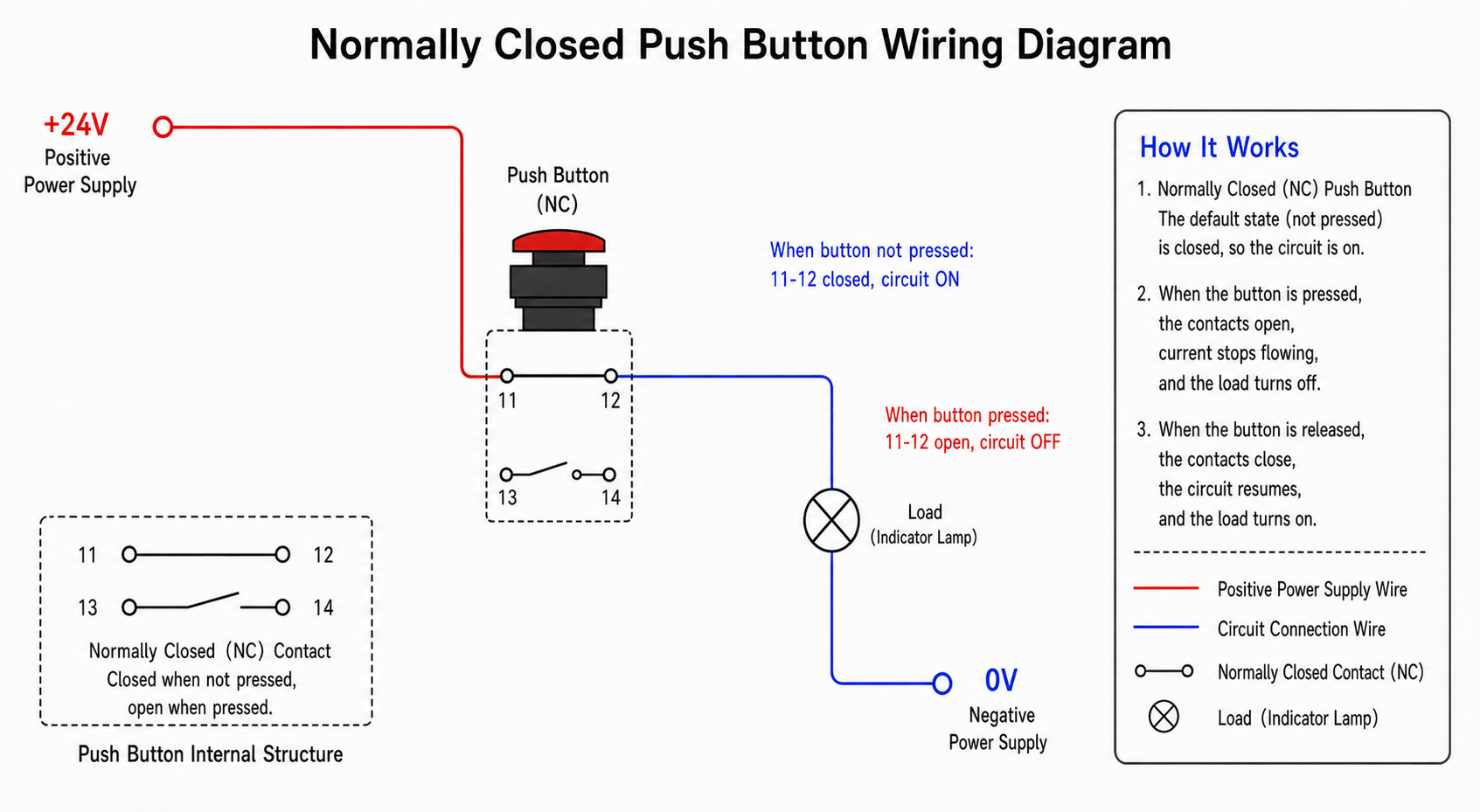
A normally closed (NC) metal push button works in the opposite way compared with a normally open push button.Under normal conditions, the internal contact remains closed, allowing electrical current to continuously flow through the circuit.
When the operator presses the button, the NC contact opens and interrupts the electrical connection.This switching method is commonly used for stop commands and safety-related applications.
- Released Button: COM and NC terminals are connected
- Pressed Button: COM and NC terminals disconnect
- Main Function: Interrupt control circuits
Simple NC Metal Push Button Wiring Diagram
24V DC +
|
|
Push Button COM
|
Push Button NC
|
Control Relay / Safety Input
|
0V DC -
In a normal condition, the NC contact keeps the circuit active.When the button is pressed, the circuit opens and the control system receives a stop signal.
Step-by-Step Connection of an NC Metal Push Button
1.Select an NC metal push button according to voltage rating, contact rating, and environmental requirements.
2.Identify the COM and NC terminals on the contact block.
3.Connect the control voltage supply to the COM terminal.
4.Connect the NC terminal to the safety circuit, relay input, or PLC input.
5.Complete the circuit by connecting the control return line.
6.Press the button and verify that the circuit opens correctly.
Industrial Applications of NC Metal Push Buttons
| Application | Usage |
|---|---|
| Machine Stop Button | Stops machine operation by opening control circuit |
| Safety Circuit | Provides fail-safe interruption signal |
| Control Cabinets | Industrial equipment stop control |
| Operator Panels | Manual stop operation |
For industrial applications, NC metal push buttons are preferred when the system requires a normally active circuit that can detect cable disconnection or contact failure.
This makes them suitable for safety-related control applications.
How to Wire an LED Illuminated Push Button?
What Is an Illuminated Push Button?
An illuminated push button is an industrial push button switch that combines two functions in one component:a mechanical switching function and an LED indicator function.
Unlike a standard push button, an illuminated push button contains an integrated LED light that provides visual feedback to operators.The LED can indicate machine status, power availability, operating conditions, alarm signals, or control commands.
Illuminated push buttons are commonly installed in industrial control panels, automation equipment, production lines, electrical cabinets, and machine operator stations.
They help operators quickly understand equipment status without checking the PLC screen or internal electrical components.
How Does an Illuminated Push Button Work?
An LED illuminated push button contains two independent electrical circuits:
- 1. Switch Circuit: The switch circuit controls the electrical signal.
It usually contains COM, NO, and NC terminals.
When the button is pressed, the contact state changes and sends a control signal to the PLC, relay, or machine controller. - 2. LED Indicator Circuit: The LED circuit controls the illumination function.
The LED terminals require a separate power supply connection, such as 12V DC, 24V DC, or AC voltage depending on the button specification.
Because the switch circuit and LED circuit are independent, the LED can be controlled separately from the push button contact.
For example, a machine start button can light green after the PLC confirms that the motor has started successfully. (The machine start button light color depends on the connection method of the product and personal preference.)
LED Illuminated Push Button Terminal Explanation
Before wiring an illuminated push button, identify each terminal correctly.
Most industrial LED push buttons use 5 terminals or more depending on the LED type and contact configuration.
| Terminal | Function | Description |
|---|---|---|
| COM | Switch Common | Common connection for the mechanical contact circuit |
| NO | Switch Output | Normally open contact output signal |
| NC | Normally Closed Output | Normally closed contact output signal |
| LED+ | LED Positive | Connect to positive power supply |
| LED- | LED Negative | Connect to negative or 0V terminal |
Example 1: 24V LED Push Button Wiring
A 24V DC illuminated push button is one of the most common configurations used in industrial automation systems.
The following example shows how to connect the switching function and LED indicator separately.
Switch Circuit:
24V DC +
|
|
COM Terminal
|
NO Terminal
|
PLC Input
|
0V DC -
LED Indicator Circuit:
24V DC +
|
LED+
|
LED Lamp
|
LED-
|
0V DC -
In this configuration, pressing the button sends a control signal to the PLC while the LED can indicate power status or machine operating status.
For example:
- Green LED ON: Machine ready status
- Red LED ON: Machine running or alarm condition
- Yellow LED ON: Warning or maintenance requirement
Example 2: Two-Color LED Push Button Wiring (Bi-Color LED)
A two-color LED push button uses multiple LED inputs to create different indicator colors.This type of button is commonly used when one switch needs to display different machine states.
Typical applications include:
- Green: Machine ready
- Red: Machine operating
- Yellow: Warning or standby
How Does a Two-Color LED Push Button Work?
A bi-color LED push button usually contains two internal LED chips.
Each LED color is controlled by a different power input terminal.
By switching the power supply between LED terminals, the control system can display different colors.
PLC Output 1
|
Green LED Terminal
PLC Output 2
|
Red LED Terminal
For advanced automation systems, the PLC program can control LED colors automatically according to machine conditions.This makes illuminated push buttons useful as compact human-machine interface (HMI) devices.
Common LED Push Button Wiring Problems
| Problem | Possible Cause |
|---|---|
| LED Does Not Light | Wrong polarity or incorrect voltage connection |
| Button Works but LED Does Not | Switch circuit connected correctly but LED circuit disconnected |
| LED Burns Out Quickly | Applied voltage exceeds LED rated voltage |
When selecting an LED illuminated push button, always confirm the LED voltage rating, contact configuration, mounting diameter, IP protection rating, and operating environment.
For industrial control panels, 22mm LED push buttons with 24V DC illumination are among the most widely used solutions.
How Does a Push Button Connect to PLC?
Push Button to PLC Control Logic Explained
In modern industrial automation systems, push buttons are commonly connected to a PLC (Programmable Logic Controller) instead of directly controlling high-power devices.
The push button acts as an operator input device that sends a signal to the PLC, and the PLC executes programmed logic to control output devices.
The complete control process usually follows this sequence:
Push Button → PLC Input → Program Logic → PLC Output → Machine Device
For example, when an operator presses a machine start button:
1.The normally open push button contact closes.
2.A 24V DC signal is sent to the PLC digital input module.
3.The PLC program detects the input change.
4.The PLC activates an output signal.
5.The output controls a motor starter, solenoid valve, relay, or actuator.
PLC Push Button Wiring Diagram
A typical industrial PLC push button wiring method uses a 24V DC control circuit.
The push button is connected to a PLC digital input terminal.
24V DC +
|
|
Push Button COM
|
Push Button NO
|
PLC Digital Input X0
PLC Program Logic
|
|
PLC Output Y0
|
|
Motor Contactor / Relay
|
0V DC -
The PLC input does not normally supply enough power to directly drive industrial loads.Instead, the PLC output controls an intermediate device such as a relay or contactor, which handles the higher current required by motors and industrial equipment.
PLC Push Button Wiring Components
| Component | Function |
|---|---|
| Industrial Push Button | Provides operator command signal |
| 24V DC Power Supply | Provides control voltage |
| PLC Digital Input | Receives button status signal |
| PLC Program | Processes input conditions and executes logic |
| PLC Output | Controls external devices |
Common PLC Push Button Applications
- 1.Machine start and stop control
- 2.Production line operation commands
- 3.Manual/automatic mode selection
- 4.Reset functions after machine alarms
- 5.Operator confirmation inputs
- 6.Robot and automation equipment control
When designing a PLC control system, engineers should consider the push button contact type, input voltage, PLC input compatibility, wiring method, and environmental protection requirements.

How to Connect Emergency Stop Button Wiring?
Why Does an Emergency Stop Button Use NC Contact?
Emergency stop buttons are one of the most important safety components in industrial machinery.
Unlike normal start buttons, emergency stop switches usually use normally closed (NC) contacts because safety systems require fail-safe operation.
A normally closed emergency stop circuit remains continuously closed during normal operation.
When the emergency stop button is pressed, the contact opens and immediately interrupts the safety control circuit.
Reasons Emergency Stop Uses NC Contacts
| Safety Principle | Explanation |
|---|---|
| Fail-Safe Design | Any interruption of the circuit can trigger a safe stop condition |
| Wire Break Detection | Broken wires cause the circuit to open and the machine detects a fault |
| Safety Reliability | Normally closed design improves fault detection capability |
Emergency Stop Button Wiring Diagram
A typical emergency stop wiring system uses an NC contact connected through a safety relay before reaching the machine control system.
24V DC +
|
|
Emergency Stop Button NC Contact
|
|
Safety Relay Input
|
|
Machine Control Circuit
|
0V DC -
When the emergency stop button is pressed:
- 1.The NC contact opens.
- 2.The safety relay detects the interruption.
- 3.The machine control power is removed or disabled.
- 4.The equipment enters a safe stop condition.
Emergency Stop Wiring Requirements
- Use NC contacts: Emergency stop circuits should use normally closed contacts for safety monitoring.
- Manual reset: After emergency stop activation, the system should require a manual reset before restarting.
- Safety relay recommended: Safety relays provide monitoring functions and improve system reliability.
- Follow machine safety standards: Emergency stop systems should comply with applicable industrial safety requirements.
Emergency Stop Applications
| Equipment | Emergency Stop Application |
|---|---|
| CNC Machines | Immediate machine shutdown during abnormal conditions |
| Robotic Systems | Operator safety protection |
| Packaging Machines | Emergency interruption of production operation |
| Industrial Assembly Lines | Safety shutdown control |
Proper emergency stop wiring is critical for machine safety.Incorrect wiring, such as using NO contacts instead of NC contacts, may prevent the safety system from detecting failures.
Common Push Button Wiring Mistakes
Although industrial push button wiring is relatively simple, incorrect connections are one of the most common causes of machine control failures.Understanding typical wiring mistakes can help engineers and technicians reduce troubleshooting time and improve equipment reliability.
Mistake 1: Confusing NO and NC Terminals
One of the most common push button wiring mistakes is connecting the wrong contact terminals.A NO contact and NC contact have opposite electrical behaviors.
For example, connecting an emergency stop circuit to an NO terminal may prevent the safety system from detecting wire failures.
Safety-related applications normally require NC contacts.
- 1.Always check terminal markings before wiring.
- 2.Use a multimeter to verify contact status if necessary.
- 3.Confirm whether the application requires NO or NC operation.
Mistake 2: Incorrect LED Polarity Connection
LED illuminated push buttons require correct polarity.
Connecting LED+ and LED- in the wrong direction may prevent the indicator light from working.
Common symptoms include:
- 1.Button switching function works normally, but LED does not illuminate.
- 2.LED indicator flickers or behaves abnormally.
- 3.Indicator failure after incorrect voltage connection.
Always verify LED voltage rating and polarity before connecting the power supply.
Mistake 3: Connecting the Wrong Voltage
Industrial push buttons are available with different voltage ratings, including 5V, 12V, 24V DC, and AC versions.Applying an incorrect voltage can damage LED indicators or internal components.
| Incorrect Practice | Possible Result |
|---|---|
| 24V LED connected to 110V AC | LED damage or component failure |
| AC and DC voltage mixed | Incorrect operation or safety risk |
| Overrated current through contacts | Contact damage or shortened lifetime |
Mistake 4: Using NO Contact for Emergency Stop
Emergency stop buttons should normally use NC contacts because safety circuits require fault detection.Using NO contacts may create unsafe conditions because a disconnected wire may not be detected.
For emergency stop applications, always consider:
- 1.Normally closed safety contacts
- 2.Safety relay monitoring
- 3.Manual reset function
- 4.Applicable machine safety requirements
Push Button Wiring Selection Guide
Selecting the correct industrial push button depends on the machine function, control logic, electrical requirements, and operating environment.The table below provides a quick selection guide.
| Application | Recommended Contact Type | Typical Example |
|---|---|---|
| Start Machine | NO Contact | Motor start button, cycle start button |
| Stop Machine | NC Contact | Machine stop control |
| Emergency Stop | NC Safety Contact | Safety shutdown circuit |
| PLC Signal Input | NO or NC | Automation control input |
| Status Indicator Button | LED + Contact | Machine status indication |
Factors to Consider When Selecting a Push Button
- Voltage Rating:
Select the correct operating voltage for the switch contact and LED indicator. - Contact Configuration:
Choose NO, NC, or combination NO+NC according to control logic. - LED Requirement:
Consider single-color or bi-color indication requirements. - Mounting Size:
22mm push buttons are widely used in industrial control panels. - Environmental Protection:
Consider IP rating, dust resistance, moisture protection, and operating conditions.
Frequently Asked Questions About Push Button Wiring
1. Under what circumstances do you need to select a normally open push button switch?
Normally open push buttons are suitable for command signals where the circuit should only activate when the operator presses the button.
Common applications include machine start buttons, PLC inputs, and trigger functions.
2. Under what circumstances do you need to select a normally closed push button switch?
Normally closed push buttons are used when the circuit needs to remain active during normal operation and open when pressed.
They are commonly used for stop functions, safety circuits, and emergency stop systems.
3. How do I wire a 5 pin LED push button?
A 5 pin LED push button usually contains three switch terminals (COM, NO, NC) and two LED terminals (LED+, LED-).
The switch circuit and LED circuit should be wired separately according to the application requirements.
4. Can a push button connect directly to PLC?
Yes. Industrial push buttons are commonly connected directly to PLC digital inputs.
However, the voltage level and input type must match the PLC specifications.
5. Why are emergency stop buttons normally closed?
Emergency stop buttons use NC contacts because they provide fail-safe operation.
If a wire breaks or the circuit fails, the safety system can detect the abnormal condition.
6. How do I test push button terminals?
A multimeter in continuity mode can be used to test terminals.
A NO contact should show continuity only when pressed, while an NC contact should show continuity before pressing.
7. What voltage is commonly used for industrial illuminated push buttons?
24V DC is one of the most common voltages for industrial LED illuminated push buttons because it is widely used in automation control systems.
8. What is the difference between a push button switch and an illuminated push button?
A standard push button only provides switching operation, while an illuminated push button includes an additional LED indicator circuit for visual status indication.
9. Can one push button have both NO and NC contacts?
Yes. Many industrial push buttons support combined NO and NC contact blocks, allowing one button to send different signals to multiple circuits.
10. How do I choose the right industrial push button?
The correct push button selection depends on voltage rating, contact configuration, LED requirements, mounting size, environmental conditions, and application purpose.
Conclusion: Choosing the Right Industrial Push Button
Selecting and wiring an industrial push button correctly is essential for reliable machine operation and operator safety.
Different applications require different contact configurations and electrical designs.
For machine start functions, normally open contacts are commonly used.
For stop and safety functions, normally closed contacts provide better fault detection.
For status indication, illuminated push buttons provide both control and visual feedback.
Before installing a push button switch, always check:
- 1.Voltage rating
- 2.Contact configuration
- 3.LED requirements
- 4.Mounting diameter
- 5.Application environment
With the correct wiring method and product selection, industrial push buttons can provide reliable control performance for automation systems, machinery, electrical panels, and industrial equipment.