
Understanding the Role of a Switch in Electrical Product Design
A switch plays a crucial role in electrical product design by managing the flow of electricity. It essentially acts as a gatekeeper for electrical circuits.
-
Controlling Power Flow: The primary function of a switch is to control when electricity can flow through a circuit. By closing the switch, you complete the circuit, allowing electricity to power the device. Conversely, opening the switch breaks the circuit, stopping the current and turning the device off.
-
Enhancing User Control: Switches provide a simple, user-friendly means to safely manage electrical connections, making them indispensable in appliances and electronic devices. They allow users to easily turn equipment on or off, adding convenience and flexibility.
-
Improving Safety: By breaking the circuit, switches prevent continuous power flow, which can be vital for maintaining safety and preventing electrical hazards. This is particularly important in home and industrial settings where the risk of overheating or short circuits is present.
In summary, switches are fundamental in the design and function of electrical products, offering control, convenience, and safety by opening and closing electrical circuits as needed.
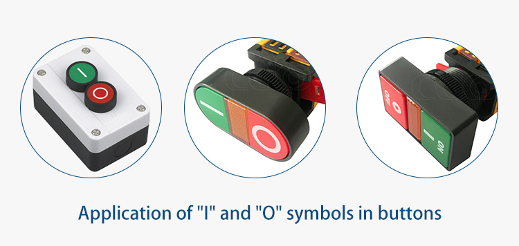
① There are two symbols "I" and "O" on the power switch of some large equipment. Do you know what these two symbols mean?
"O" is power off, "I" is power on. You can think of "O" as the abbreviation of "off" or "output", which means off and output, and "I" is the abbreviation of "input", that is "Enter" means open.
But why these particular symbols? An easy way to remember this is through binary logic: 0 = false, meaning no power or off; and 1 = true, or on. In the case of I/O, the "I" represents 1. So, if a switch is turned to "I", it's in the On position. If it's turned to "O", it's in the Off position.
② So where did these two symbols come from?
In order to ensure the stable operation of electrical equipment during World War II, it was necessary to unify the switches of electrical equipment in various fields such as the army, navy, air force, and logistics, as well as the standard of the selector switch. In particular, the identification of switches needed to ensure that soldiers and maintenance workers in various countries could recognize and use them correctly after only a few minutes of training.
An engineer thought that the problem could be solved by using the binary code that was commonly used internationally at that time. Because binary "1" means on and "0" means off. So, there will be "I" and "O" on the switch.
In 1973, the International Electrotechnical Commission (IEC) officially suggested that “I” and “O” should be used as the symbols of the power on-off cycle in the technical specifications compiled. These symbols are now widely recognized and appear in the IEC 60417 standard for on/off switch markings. The symbol for ON is “I” (a straight line), signifying that the circuit is closed and power is flowing. Conversely, the symbol for OFF is “O” (a circle), indicating that the circuit is disconnected.
These visual cues help users easily identify the operational state of a device. It is important to note that the orientation of these symbols can vary depending on specific equipment standards. Some guidelines may require that the “I” be installed in a vertical position to signify the ON state. In my country, it is also clear that “I” means the circuit is closed (i.e., open), and “O” means the circuit is disconnected (i.e., closed). This intuitive design ensures that users can operate switches with confidence, knowing the exact state of the device they are controlling.
Common Locations of Power Buttons on Electronic Devices
Power buttons are thoughtfully positioned on various types of computers and electronic devices to ensure easy access and intuitive operation.
- Desktop Computers: You’ll commonly find the main power button on the front of the computer case. Additionally, there’s often a separate power switch for the power supply located on the back of the case, providing an extra layer of control.
- Monitors: For most desktop displays (like those from Dell, HP, and Samsung), the power button is typically found on the lower bezel—either along the front, side, or occasionally tucked just underneath for a streamlined look.
- Laptops and Netbooks: The power button usually sits along the top row above the keyboard or integrated into the side of the body, sometimes subtly designed as part of the keyboard itself.
- Tablets and Mobile Devices: On these portable devices, power buttons are generally located on the side or top edge, positioned for convenient access whether you’re holding the device in portrait or landscape orientation.
This thoughtful placement ensures users can power devices on or off quickly, contributing to both convenience and safety in daily operation.
③ How to choose a button switch?
What Are the Different Types of Switches Available?
Switches are essential components in electrical circuits, and selecting the right one depends on your specific needs. Each type of switch serves a unique purpose based on the number of circuits it controls.
Understanding Switch Circuits
At the most basic level, switches can be classified based on how many circuits they manage. A single-pole switch manages one circuit, while a double-pole switch manages two circuits, essentially functioning like two single-pole switches combined.
Key Types of Switches
To make an informed decision, let's explore the primary classifications of switches:
-
Single-Pole, Single-Throw (SPST)
- Function: This is the simplest type of switch. It operates one circuit and provides an on/off function. It's commonly used for controlling lights where basic functionality is needed.
-
Single-Pole, Double-Throw (SPDT)
- Function: This switch can route a single circuit to one of two paths. It's ideal for scenarios where you need to switch between two different outputs or devices from a single input source.
-
Double-Pole, Single-Throw (DPST)
- Function: A DPST switch controls two separate circuits simultaneously. It either opens or closes both circuits at once, often used in industrial settings where dual circuit control is necessary.
-
Double-Pole, Double-Throw (DPDT)
- Function: This versatile switch can control two separate circuits, each capable of being connected to one of two different outputs. Think of it as two SPDT switches united, suitable for complex circuitry arrangements or reversing motor directions.
Hard Power Buttons vs. Soft Power Buttons
When selecting a switch, it’s helpful to understand the distinction between hard and soft power buttons. A hard power button is a physical, mechanical switch. You can actually feel a tactile “click” when you press it, and the button itself typically changes position, letting you see and feel whether the device is powered on or off. This type of button directly connects or disconnects the electrical circuit—think of the classic rocker switch on a power strip or the main power switch on desktop computers.
In contrast, a soft power button operates electronically rather than mechanically. Pressing it may not produce a noticeable physical change, and the button often looks the same whether the device is active or not. Instead of physically cutting power, a soft button sends an electronic signal to circuitry inside the device, instructing it to power up or down—like the sleep or power buttons on modern laptops and gaming consoles. Soft power buttons allow for additional features, such as remote operation or enabling the device to perform shutdown procedures before completely turning off.
Understanding this difference can help you decide which type of power switch best suits your project, especially if you need either a direct, fail-safe operation or advanced control features.
Selecting the Right Switch
Choosing the correct switch depends on your project's demands. Consider the number of circuits, the complexity of operations, and the specific applications for which the switch will be used. Understanding these basics will lead you to the perfect switch for your electrical needs.
1. Combined material
Common plastic switches, although insulating, are flammable and prone to safety hazards. It is recommended to choose a switch with stainless steel inlaid on the surface to fundamentally prevent contacts and improve safety.
2. Combine scents
Choose a colorless and odorless PC plastic power switch.
3. Combined logo
Choose products with 3C、CE certification.
4. Combine button sounds
When using the switch, choose a power switch with crisp sound and no stagnation feeling.
5. Combine product appearance
The selection button has a bright, flawless, black-spotted surface. The appearance should be smooth and smooth, and the color should be uniform.
When discussing circuit control, a single-pole switch is used to control a single electrical circuit. Essentially, it's the most straightforward type of light switch you'll encounter. Designed for on/off functions, this switch operates just one line of electrical energy, making it ideal for simple, everyday lighting applications.
In contrast, other switch types, such as double-pole switches, manage more complex setups by controlling two circuits simultaneously. However, if you just need to toggle a single light or appliance, the single-pole switch is your go-to solution.
Its ease of use and installation makes it a favorite for basic home and office electrical systems. Remember, with a single flick, you're directing the flow of electricity through just one circuit, providing the simplicity many households require.
④ How to Install the Power Switch?
1. Before installing the power switch, it is necessary to turn off the main power supply in the home to avoid the danger of contacts;
2. Before installation, check whether the accessories of the power switch are complete;
3. Distinguish the difference between the wires, which are the live wire, the neutral wire, and the ground wire. Combine the wiring method of the power switch pins terminal to correctly link the circuit;
4. After the button switch is installed, use the testing instrument to check to ensure that the switch is normal.
On/off markings on a switch actuator are typically located either at the end of the actuator or directly on its face. The actuator, which is the component used to manually toggle a circuit, often features these markings in a highly visible spot. Generally, the face of the actuator is the most common and easiest place to find these indicators.
The markings themselves might be applied using ink or paint, or they could be integrated into the design by being molded. However, be aware that molded-in markings can be more challenging to discern compared to painted or printed ones.